Hardware, BOM, and Enclosure
Visual Asset Set
Image |
Intended use |
|---|---|
|
Homepage overview and project landing page. |
|
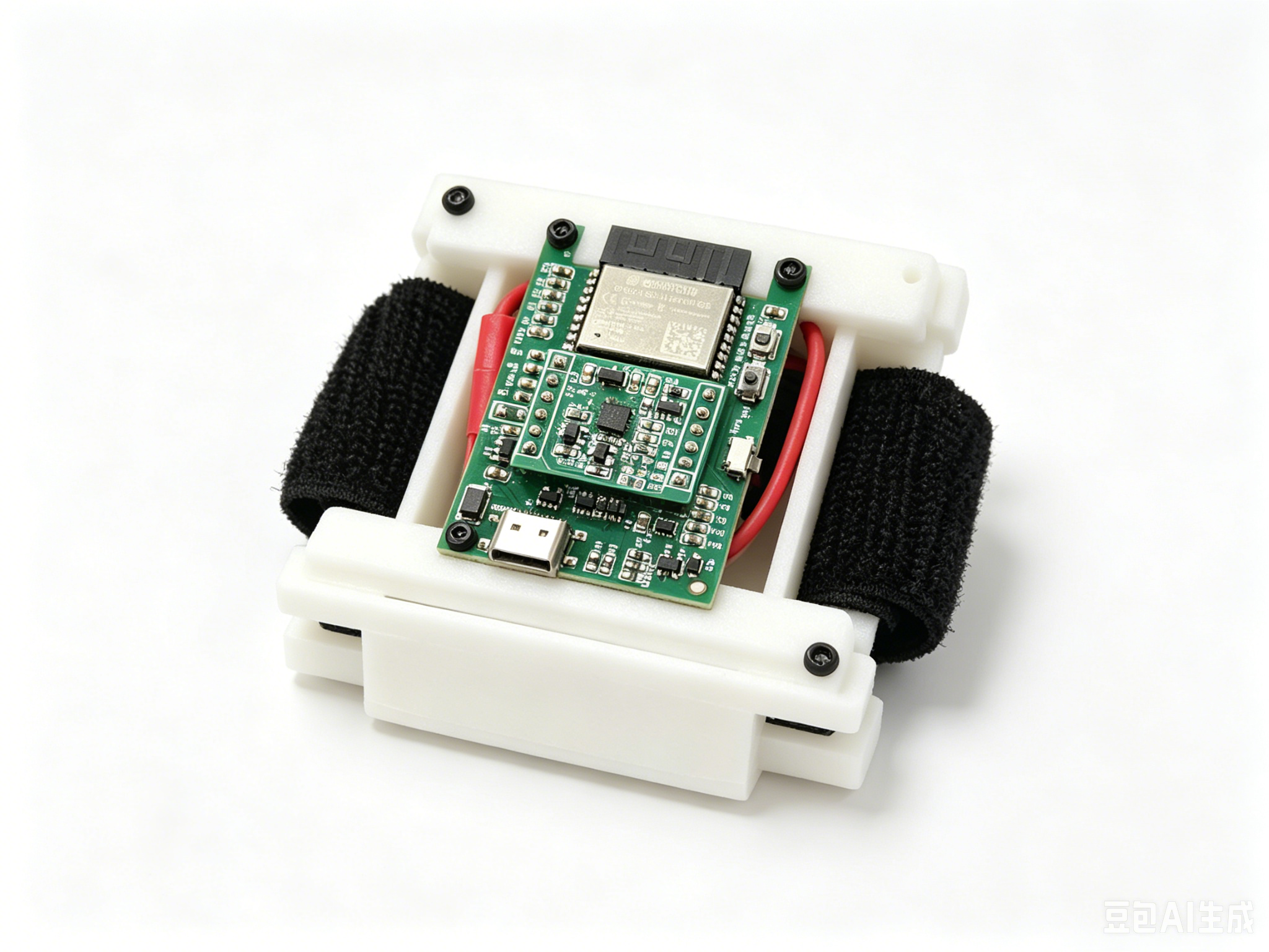
Public hardware photo for the tracker body. |
|
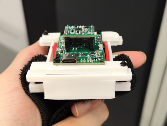
Close-up top view of the wearable board and mounting. |
|
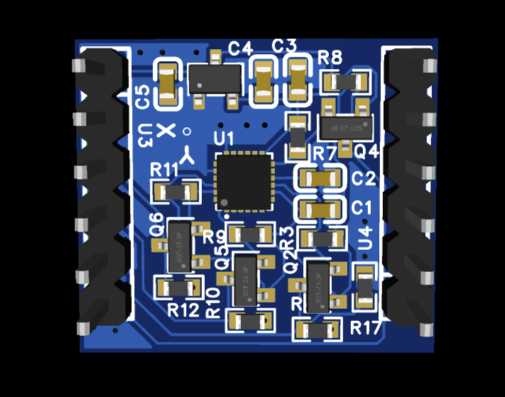
3D preview of the IMU module and enclosure fit. |
|
IMU board rendering and enclosure discussion. |
|
Sensor circuit and axis-reference explanation. |
|
ESP32-C3 transport board photo. |
|
PCB layout and component placement. |
|
Power and transport-board schematic. |
|
Full board function overview. |
Included Design Assets
Asset |
Location |
License |
|---|---|---|
ESP32-C3 transport board |
|
CERN-OHL-S-2.0 |
ICM-20948 test board |
|
CERN-OHL-S-2.0 |
Battery enclosure |
|
CC BY-SA 4.0 |
Connector enclosure |
|
CC BY-SA 4.0 |
Public bill of materials |
|
Repository default, verify suppliers yourself |
BOM notes |
|
Repository default |
Historical sourcing sheet |
|
Source reference only |
The public website should prefer the image set above for layout and explanation. Use the photo assets for product identity, and keep the schematic/PCB assets for board-level explanation.
Visual Gallery
The EPRO2 files are for Lichuang EDA. Review every schematic, footprint, net class, battery-polarity marking, and manufacturing rule before ordering.
The normalized BOM describes two configurations: a four-node minimum tracker
(chest, upper_arm, forearm, palm) and the current five-node standard
tracker with finger. Supplier links are references and must be checked before
ordering.
Current Board Connections
GPIO |
Function |
|---|---|
IO5 |
Battery-voltage ADC; the measured value is scaled by two in the board design. |
IO6 / IO7 |
I2C SDA / SCL for the IMU. |
IO1 |
ICM-20948 data-ready interrupt. |
IO2 |
Button voltage input. |
IO10 |
System-enable latch. |
The ICM-20948 test-board silkscreen has a known X/Y labeling issue. Use the sensor datasheet and a physical check, not the silkscreen alone, when defining sensor axes.
Before Powering a Board
Inspect battery polarity and charging/protection circuitry.
Verify I2C continuity and pull-up voltage before inserting the sensor.
Confirm that the board target is ESP32-C3 and that flash size matches
partitions.csv.Start with USB power and serial logs before battery-only operation.
Do not use unverified hardware on a person or near a moving robot.